This mechanism operates on a hair trigger
principle. It is operated by
a trip wire attached to the spindle.
It was intended for use with movable objects, windows, chairs,
pieces of equipment or weapons, souvenirs or any other item that was
likely to be moved.
The base assembly contains a 1.7 grain detonating
cap, No. 27 service detonator and standard C.E. primer.
It is screw threaded to screw into the upper housing.
It is common to all the trip mechanisms.
As an alternative a fuse adapter is provided that screws into the
base of the assembly that allows either instantaneous or safety fuse to
be crimped in and ignited by the mechanism.
There is an “L” shaped bracket that can be used to
fix the mechanism. There are
four holes in the back of the bracket so it can be nailed into position.
On the lower bracket a hole in the centre is used to attach the
bracket to the mechanism.
The upper housing fits on top and the base assembly screwed up through
the hole to hold the device.
This mechanism operated on the ball release
principle. It could be
operated by a direct downward pressure, release of pressure, or by a
twist applied by means of a trip wire.
The
upper housing contains the operating parts of the mechanism.
It is made of an alloy in two parts, an inner casing and an outer
casing. The inner casing
houses the firing pin, firing pin spring and retaining ball.
The firing pin is held by the retaining ball riding in a groove
in the striker and a hole in the inner casing.
The outer casing is cast with a wider head and a central ring
around the lower half. The
outer casing fits over the inner casing covering the hole in the inner
casing and holding the retaining ball in.
The firing pin spring is compressed against the firing pin and a
stud on the interior of the top of the outer casing.
There are two holes, upper and lower, in the outer casing that
line up with the hole in the inner casing in two positions.
On the opposite side to the holes there is a “Z” shaped slot with
a setting stud screwed through the slot into the inner casing.
A safety bolt fits through both casings in the lower section.
Two firing pin springs are supplied with the
mechanism, one giving an operating force of 4 pounds, the other to give
an operating force of 12 pounds.
The base assembly contains a 1.7 grain detonating
cap, No. 27 service detonator and standard C.E. primer.
It is screw threaded to screw into the upper housing.
It is common to all the trip mechanisms. As an alternative a fuse
adapter is provided that screws into the base of the assembly that
allows either instantaneous or safety fuse to be crimped in and ignited
by the mechanism.
There is an “L” shaped bracket that can be used to
fix the mechanism. There are
four holes in the back of the bracket so it can be nailed into position.
On the lower bracket a hole in the centre is used to attach the
bracket to the mechanism.
The inner housing fits on top and the primer housing is screwed up
through the hole to hold the device.
This mechanism can be used for pressure, release,
or pull operations. To use
in the pressure mode, the setting stud is moved to the “PRESS” position
in the “Z” shaped slot.
Depending on the spring used a pressure of 4 or 12 pounds will push down
on the head, forcing outer housing
down and bringing the upper hole in the outer casing in line with
the hole in the inner housing.
This allows the retaining ball to move outward and release the
striker to move down under pressure of the firing pin spring to hit the
primer and fire the mechanism.
To use in the release mode, the setting stud is moved
to the “LIFT” position in the “Z” shaped slot.
Again, depending on the spring used, a weight of over 4 or 12
pounds is placed on the mechanism.
When the weight is removed, the spring will force the outer
housing up, bringing the lower hole in the outer casing in line with the
hole in the inner housing.
This allows the retaining ball to move outward and release the striker
to move down under pressure of the firing pin spring to hit the primer
and fire the mechanism. For
use as a pull mechanism, the setting stud is moved to the “PRESS”
position in the “Z” shaped slot.
A trip wire is attached to the central ring in such a manner that
a light pull on the wire will rotate the outer housing to the “LIFT”
position and since there is no weight to restrain it, the device will
then operate as a release mechanism.
Trip Mechanism No. 6
This is a very simple mechanism, it consists of an
alloy housing that contains a spring loading striker.
A wire attached to the striker protrudes from the top of the
mechanism and is used to cock the mechanism.
The striker is held in the cocked position by the end of a
special composition wire.
There are two feet of the wire supplied with the mechanisms wrapped
around the mechanism when issued.
The wire fits through holes in the side of the housing and firing
pin. No other safety device
is fitted.
For use, a standard trip wire is attached to the
free end of the special composition wire.
A pull on the trip wire will withdraw the wire from the mechanism
freeing the striker to drive down under influence of the striker spring
to hit the percussion cap and fire the mechanism.
For the device to operate the wire had to be completely withdrawn
from the mechanism.
This was a simple igniter, used
normally to ignite safety or instantaneous fuse.
It was possible to use it as a pull switch.
This was available for use at the start of WWII and was used for
many years, examples dated 1953 have been noted.
It consists of a brass barrel
with threading on both ends.
On the top end it has a cap with a hole through the centre for the shaft
of the striker. On the other
end is a threaded cap to retain the fuse adapter.
A striker with spring is inserted with the shaft protruding out
the top and a safety pin fitting through the shaft.
The safety pin holds the striker in the cocked position with the
striker spring compressed.
Initially known only as the
"Pull Switch" this device was designed near the end of 1939 by Lt. Col.
Stuart Macrae of M.D.1 (Military Department 1).
It came about because the only device the British had to set off
a boobytrap with a trip wire was the standard service igniter, a device
actually designed to replace matches for lighting a length of safety
fuze. The service igniter
worked perfectly well for the purpose it was designed but left something
to be desired as a boobytrap device.
Lt. Col Macrae in fact designed
the pull switch from a shirt stud that worked in a way that he
considered quite clever. The
stud had a detachable head that remained firmly in place normally but
when a centre pin was pulled out could easily be removed.
The head was attached to a thin split tube with the end slightly
bulged out. The body of the
stud was a hollow button with another small tube projecting out from it.
The stud was assembled by pulling out the centre pin as far as
possible, pushing the split tube through the other tube until it passed
through and pushing in the centre pin again.
Pushing in the centre pin expanded the split tube so that it
would not pass through the other tube until the centre pin was pulled
out again. It was from this
small device that Macrae got the idea of how to design the pull switch.
Once Macrae had the idea he designed the pull switch in an hour.
The prototype was made the next day and two weeks later MD1 was
in full production of the switch.
It was a very successful design that worked perfectly from the
start. Over three million
were made during the war at a cost of 2/6d.
It is a measure of its success that it was not redesigned
throughout the war but remained in its original form.
The official description of the
switch was: "The Pull
Switch is a device to be used in conjunction with a trip wire for firing
a mine. It is particularly
useful for booby trap work.
Designed to operate when a direct pull of about 4 lbs is applied to the
release pin it fires a percussion cap in a holder exactly the same as
that supplied wit the Mk. III Service Igniter.
With the cap holder in position the switch measures approximately
4" overall by 5/8" in diameter and weighs 2 ½ oz.
It consists of a head into which is screwed a housing tube
containing a plug with a restricted opening.
At the other end of the tube is a screwed collar for attachment
of the cap holder. Inside
the housing tube is a striker head attached to a hollow spindle, which
runs inside a compression spring.
The end of the hollow spindle carries a small head which is
split, so that when it is compressed the diameter is reduced.
When this split head is forced through the small hole in the
housing tube plug, a spring loaded release pin at once enters and
expands the head so that it cannot return, although it is now under the
influence of the compression spring.
The device consists of a brass
tube threaded on both ends.
A threaded collar on the bottom end holds a standard fuze adapter with
percussion cap. The upper
end has a threaded housing that is fitted with the release pin and
spring. A brass plug with a
hole through the centre is fitted into the top end of the brass tube
before the housing is screwed on.
A striker and striker spring fit in through the bottom of the
tube. The split stem of the
striker fits through the plug up into the housing until the release pin
penetrates and expands the striker stem.
A safety pin fits through the housing and release pin preventing
it from moving. A split ring
is fitted through a hole in the end of the release pin so a trip wire
can be easily attached. An
anchor bracket may or may not be fitted by removing the collar and
slipping the bracket over the tube and replacing the collar.
The original pressure switch was
designed by Millis Jefferies (Later Major-General Sir Millis Jefferies,
K.B.E., M.C.) in early 1939.
His first pressure switch, originally designed for destroying railway
lines, was based on a large brass casting.
It used a conventional spring-loaded striker in a partitioned
barrel. The striker was
maintained in the cocked position by a steel rod that had been hardened
to the point of brittleness.
The rod was secured to the closed end of the barrel with a pin.
It ran through the partitioned off section and had the spring and
striker head after the partition.
A hole with a boss bearing was placed over the partitioned off
section. A plunger was
dropped into the hole so that its "V" end straddled the hardened steel
rod. A safety pin fit
through the boss and plunger preventing the plunger from being
depressed. While the
design of the switch was good, it was too heavy to be practical.
It was redesigned to become a device weighing only 6 ounces and
costing only 3/6d.
The pull switch as designed and
issued by MD1 was constructed of brass except for the steel rod, striker
head, and striker spring.
The barrel is cast as one piece with an enlarged section at the closed
end. The opposite end is
drilled out to a depth of about 2 inches to form the barrel.
The bottom of the enlarged section is flattened and is drilled
out from the bottom to form a partitioned section.
A hole is then drilled from the top for the plunger.
A small hole for the steel rod is drilled from the closed end
completely through into the barrel.
The barrel is threaded on the open end to fit a screwed collar.
The base plate is a 1/8 inch rectangular piece of brass that is
attached by two bolts to the flattened portion of the barrel.
There are five holes in the base plate, two countersunk holes for
the bolts, two in opposite corners to allow the switch to be screwed in
position, and one large one to hold the pressure plunger in transit.
The pressure plunger is turned out of brass with a stem and large
pressure head. The bottom of
the stem is slotted for a short distance and has the bottom of the slot
formed into a "V" shaped cutting head.
A safety pin passes through the stem.
The steel rod is assembled with
the striker head and striker spring.
It is passed through the hole in the barrel assembly compressing
the spring. It is then
pinned in the cocked position.
All holes into the partiioned section are then sealed with
sealing wax.
The Mk. II version of the pressure switch has a body and base cast from alloy in a single piece. A small boss is formed on the top of the body to accept the pressure plunger. The safety pin is fitted through holes in the boss and through the pressure plunger. Because of this design change the plunger is assembled to the body when issued rather than being held in the base plate as in the Mk. I version. In addition the switch has improved waterproofing
This switch was also designed by
Lt. Col Stuart Macrae of MDI.
It was another of the successful devices that worked correctly
the first time and needed no improvements throughout the war.
From design to full production took only two weeks.
About two million were made during the war at a cost of 2/3d
each.
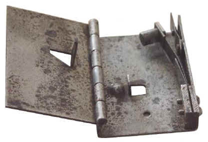
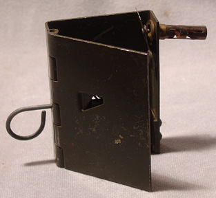
The switch resembles a small box
with a hinged lid. The main
casing is constructed of sheet steel and has a lid, hinged on the long
side of the box. There are
two punchouts in the body, one in the bottom that is rectangular and
bent up to form a bracket for the safety pin.
The other is in the lid and has an angled side forming part of
the release mechanism of the switch.
There is a hole drilled through the base to allow it to be
screwed or nailed in position.
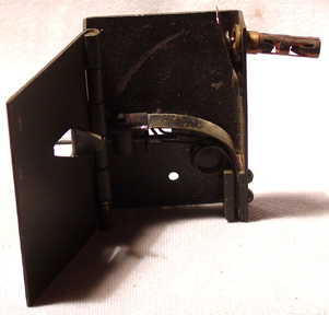
A strong leaf spring with a hammer head mounted on the free end
is attached on the side of the box opposite the hinge.
An additional half length leaf spring is attached on top of the
leaf spring to give a stronger spring.
The springs are retained in position by two small bolts that
screw into a small rectangular plate over the end of the springs.
The hammerhead attached to the end of the longer spring has a
large hole drilled through the head to correspond with a hole in the
side of the case and a hole in the anchor tab.
The safety pin fits through the case, then the hammerhead, and
finally the tab to retain it in the cocked position.
The opposite end of the box has a hole to accept a fuze adapter.
A short piece of spring steel with a striker mounted is riveted
in position so that the striker is positioned over the hole where the
percussion cap of the fuze adapter would sit.
This piece also serves to keep the fuze adapter in position after
it is fitted.
The switch is painted olive
green with no other markings.
The switch may or may not be stamped with an "MD1" mark.
This is the original design of
the switch and is only known as the "Release Switch".
It was used prior to official adoption as a service store.
The switch that was adopted as
a service store as the No. 3 Mk. I is slightly modified from the earlier
release switch. This version
has the second shorter piece of spring steel shortened and an additional
wire spring fitted to give a stronger hit when released.
The switch is painted olive
green with no other painted markings.
The only other mark is the British Broad arrow marking.
The use of the switches is
identical. For use, it must
be cocked by drawing back on the hammer head until the safety pin can be
inserted and retain it in the cocked position.
At this point the pressure placed on the safety pin makes it very
difficult to remove. A fuze
adapter or spring snout is then inserted in the hole at the end of the
box under the firing pin.
The fuze is placed in position and the charge attached.
An object weighing at least 1.5 lbs is then placed on the top of
the lid. This forces the lid
down which forces the inclined tab on the lid to push the spring back
slightly. This action
releases the safety pin allowing it to be easily removed.
When removing the safety pin, if there is any resistance, the
switch is not laid properly and must be reset.
If the safety pin comes out without resistance, it is laid
correctly.
This switch was designed by
Experimental Station 6; a cover name for the SOE production
establishment. Originally
known as "Type 6 Pull" it was designated No. 4 Mk. I when it became a
service store in 1942/43.
It remained in service for a great number of years after the war,
being used well into the 1980's, and may still be in service.
Switches dated as late as 1984 have been noted.
The mechanism consists of a
brass body with a clip bearing two eyes attached near the bottom end.
The bottom end is internally threaded to accept a "Snout, Switch,
Capped Mk. 1". The top end
has two elongated slots opposite each other and has an internal
constriction formed at the bottom end of the slots.
The striker has a shoulder and firing pin formed at one end and a
rounded head at the other. A
safety pin hole is drilled through the rounded head.
A "U" shaped clip is formed in such a manner that the ends
conform to the rounded head of the striker.
When assembled the striker and
striker spring are put in through the bottom end of the body and forced
up through the constriction far enough so the head protrudes past the
top end of the body. The "U"
shaped clip is put over the head of the striker and the striker allowed
to move back into the body.
At this point the clip will not open enough to release the striker to
pass back through the constriction.
A safety pin is pushed through the slots in the side of the body
and through the hole in the striker head to ensure the device remains
safe.
The body is left with the
natural brass colour although a varnish is applied.
The body is marked in black with the designation, manufacturers
mark, date of manufacture, and lot number.
When the switch is set with a
trip wire, a tension is put on the line to pull back on the "U" shaped
clip so the safety pin will come out easily.
At this point the safety pin will be somewhere near the centre of
the elongated slots. With
the safety pin out: if a pressure or pull of six to eight pounds is
applied to the trip wire, it will pull the "U" shaped clip and the
striker with it, out of the body.
When the clip clears the top end of the body it will release the
striker to move forward under pressure of the striker spring.
The firing pin strikes the percussion cap and sets of the trap.
This switch was designed by
Experimental Station 6; a cover name for the SOE production
establishment. Originally
known as "Type 6 Pressure" it was designated No. 5 Mk. I when it became
a service store in 1942/43.
It remained in service for a great number of years after the war,
being used well into the 1980's, and may still be in service.
It has been in British and Canadian Service and possibly with the
American OSS as "Firing Device-Pressure Type A3".
The switch consists of a steel
case with a hinged steel lid fitting inside the case.
A zinc alloy body is fixed inside the case by a countersunk bolt.
The end of the body is threaded to accept a " Snout, Switch,
Capped Mk. 1". There are two
holes in the bottom of the case for use in securing the switch.
Two studs on the bottom of the case keep the sear springs in
position. The lid has a
centre threaded hole to screw an extension into.
The striker is formed with a shoulder and firing pin on one end
and a detent on the other.
The sear is formed of steel and has two studs riveted on to correspond
with the studs on the case to retain the sear springs.
A safety pin passes through the case, body, and striker to ensure
the device will not fire when it is in position.
An extension rod is made in two
parts, a brass socket that screws into the top of the lid and a steel
rod that screws into the socket.
The extension is adustable in height by about one inch by varying
the amount that the rod is screwed into the socket.
If a shorter extension is required, the socket may be used
without the rod.
WWII issued switches are painted
dark green, postwar switches are painted tan with markings in black.
Markings give the designation, manufacturers mark, date of
manufacture and lot number.
When the switch is assembled,
the striker and striker spring are inserted in the end of the body with
the detent facing down. The
striker is pressed back until the detent engages the sear and holds the
striker in the cocked position.
The safety pin is then passed through the holes in the side of
the body to make the switch safe.
The pressure necessary to
operate the device varies with the position the pressure is applied on
the lid. At the farthest
from the hinge pin it requires a pressure of 21 pounds, at the centre a
pressure of 50 to 60 pounds is required.
When pressure is applied to the switch the lid presses down on
the sear, when the sear is pressed down it disengages from the detent
allowing the striker to fly forward under pressure of the striker
spring. The firing pin hits
the percussion cap and fires the charge.
This switch was designed by
Experimental Station 6; a cover name for the SOE production
establishment. Originally
known as "Type 6 Release" it was designated No. 6 Mk. I when it became a
service store in 1942/43.
It remained in service with British and Canadian forces for a
number of years after the war, being used well into the 1980's, and may
still be in service. Also
listed as an issue item to the American OSS during WWII.
The switch consists of a zinc
alloy body threaded at one end to receive the "Snout, Switch, Capped,
Mk. 1". The other end is
flattened to allow it to be inserted into narrow openings.
A hole drilled in the flattened end enabled the switch to be
fastened in position. A
steel lid is hinged at the threaded end an fits over the body.
The sear is hinged at the opposite end.
The striker is formed with a sholder and firing pin at one end
and a detent cut on the other.
A safety pin hole is drilled through the body and another through
the striker.
The switch is painted dark green
with markings in black.
Markings give the designation, manufacturers mark, date of manufacture,
and lot number.
When assembled, the striker and
striker spring are inserted in the threaded end with the detent facing
up. The striker is pushed
back until the sear engages in the detent and holds the striker.
The safetly pin must be put in place or the switch will operate.
The safety pin is the only thing holding the switch in the cocked
position at this point.
When the switch is set in
position and a weight of 3.5 lbs minimum is applied to the lid, it
forces down on the lid and sear it forces the striker back slightly
releasing the safety pin.
The safety pin can then be easily removed without force.
A seven pound weight is the minimum weight recommended to hold
the switch.
This is an
electrical contact switch introduced for service in 1941.
It can be used as a pressure or pull switch.
It is used only with electrical detonators.
The main body is a
flat tin with the top soldered on and a cap on the bottom to allow a
“Battery, Dry, W, Mk. I” or a standard 3 cell flat torch (flashlight)
battery to be fitted.
It has two mounting rings soldered to either side just below the top.
There are two electrical terminals on the top of the switch.
Mounted on the flat side is the operating mechanism with a
plunger. The plunger has a
switch bar internally and a brass plate on the external end.
The plate has two holes for attachment of a trip wire and a
central threaded hole for an extension rod.
The tension required to operate the switch can be adjusted by a
ball release catch located on the side of the plunger housing.
It is adjusted by screwing in or out a setting stud.
A safety pin with a lock nut fits through the plunger housing and
plunger preventing its movement.
The safety pin cannot be removed unless the plunger is in the
neutral position and held by the ball release catch.
The minimum
operating tension is about 2.2 Kg and can be adjusted up from that.
The switch is
painted olive green and has a white star marked in the centre of the
body In addition the
positive and negative terminals are marked in red and black on the side
of the case.
When the device is
laid, pressure on the brass plate will cause it to move downward pushing
the plunger in. When the
plunger is pushed in, the switch bar will connect with contacts within
the device and complete the circuit.
If used as a pull device, a pull on the trip with will cause the
plunger to pull outward causing the switch bar to connect with two other
contacts within the device and complete the circuit.
Developed by MD1 production of this switch commenced in January of 1940. It is in reality a small anti-personnel land mine that was also useful against wheeled vehicles. It was designed to be laid in paths, roads, and tracks so that when pressure is applied it would fire a bullet upwards through a man’s foot or into a tire.
The switch is
comprised of a hollow metal spike with a flange at the top end.
In the earliest versions the flange is attached to the spike, in
later versions the spike is belled out at the top and a washer slipped
over the spike being held in place by the belled out portion.
The firing mechanism is inserted into the spike.
It consists of a metal spindle with a flange at the base and an
umbrella catch at the top. A
firing spring and spring retaining sleeve are threaded over the spindle
and held in compression by the umbrella catch. Once the firing mechanism
is inserted, a striker with a short sleeve on the bottom is inserted
with the sleeve over the spindle.
When the spike is
driven into the ground, the switch is carefully loaded with a special
cartridge that rests on top of the striker with the point of the
cartridge protruding above the switch.
When a pressure of about 4 pounds is applied to the top of the
cartridge it pushes it down forcing the striker down.
The sleeve on the striker contacts the umbrella catch and forces
it in to release the spring retaining sleeve.
Once released the firing spring forces upward on the retaining
sleeve which then hits the sleeve on the bottom of the striker with a
sharp blow. The blow is
transmitted to the striker head and thus the percussion cap in the
cartridge causing it to fire.
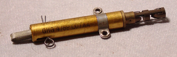
This delay switch was developed by MD1 in February 1940 and was in full production from October of 1940. It is based on the fact that Tellurium lead under load, will stretch uniformly and eventually break.
The
switch is housed in a tubular body made either of brass or steel.
The lead rod is turned down to form a small dumbbell shaped
element that is then pegged at its upper end into a brass collar.
The brass collar is then crimped into the top end of the body
tube. The striker pin is
pegged into a brass collar at its upper end which has the lower end of
the lead element pegged into it.
This brass collar is an easy sliding fit in the body tube.
The tension spring is attached to another collar that has a guide
tube for the striker attached and is crimped into the bottom end of the
body tube. The upper end of
the spring is hooked into a slot in the upper end of the striker.
At this point the spring is under tension.
An adapter or spring clip with percussion cap or 1.7 grain
detonator is crimped into the extreme bottom of the body tube.
The starting pin fits through the body and striker collar
preventing movement of the collar and thus relieves any tension being
put on the lead element. A
small clip on the end of the starting pin prevents it from falling out
accidentally. A small
plastic tab on the starting pin gives the delay time of the switch.
When the starting
pin is removed, tension is transferred to the lead element.
The lead begins to stretch and will eventually break releasing
the striker to hit the cap to ignite a fuse or fire the detonator.
This switch was also developed
during the latter part of the Second World War.
It was also on issue to the American OSS during the war.
It is likely that the American M1 Delay Firing Devicewas designed
from this switch being modified only by fitting an American Base Coupler
to it instead of the spring snout.
When the switch is to be used,
either a detonator can be fitted to the spring snout or a piece of
safety fuze. Before use the
switch must be examined by looking through the inspection holes to
ensure the striker is still held in position.
If not, the switch is discarded.
When laid the upper copper portion of the casing is crushed from
both sides, this causes the glass ampoule to break and release the
corrosive liquid. The
corrosive liquid acts on the retaining wire eventually weakening it
enough to break under the pressure of the striker spring.
When the wire breaks the striker, under pressure from the striker
spring is forced down onto the percussion cap.
The percussion cap fires igniting either the safety fuze or
detonator.
The safety strip is colour coded according to the nominal delay of the switch. When initially developed there were six different delay periods that were later reduced to the three listed below. The nominal delay times for the earlier switches were timed at 77 degrees fahrenheit. The delay strips were painted in six different colours giving delays of: black 10 min, red 19 min. White 1 hr 19 min., Green 3 hrs 10 min, yellow, 6 hrs 30 min. and blue 14 hrs 30 min. Later issues eliminated three of the delays leaving the following: A white strip gives a delay of 1.5 hours, yellow a delay of 6 hours, and blue a delay of 16-18 hours timed at 65 degrees fahrenheit. The delay times are effected by atmospheric temperatures.
The switch is normally
unpainted, the top is natural copper coloured, the bottom portion
depending on the age of the switch may be grey in the earliest models,
silver, or brass coloured.
The safety strip is painted to denote the delay times as listed above.
The switches were initially
issued in tin boxes containing 5 switches of the same delay period, the
tape sealing the box was the same colour as the safety strips.
This switch was designed during
the Second World War as an electrical contact anti vehicular pressure
switch. It is designed to be
laid across a road to destroy wheeled or tracked vehicles.
Because it is an electrical switch the charge can be a
considerable distance from the switch if required.
It consists of two sections 2'
9" long connected by a flexible electrical wire 6" long.
Each section consists of two strips of brass held apart by
insulating spacers every six inches.
The strips are contained in rubber tubing closed at the ends by
rubber plugs. One section
has two additional electrical leads fitted with plugs coming out of it
to connect to the battery.
Each set comes complete with a 9 volt battery.
The battery is specially designed with sockets for the leads from
the switch and two screw terminals that will connect to an electrical
detonator.
The tubing covering the brass
contact strips is red. This
switch must be concealed or it will be easily seen on the road.
It must either be painted or covered with a thin layer of dirt or
grass. It must not be
buried.
This switch was
developed and manufactured by MD1 and introduced in 1943 as an anti-lift
device to be placed under anti- tank mines.
It was in fact a combination of the AP Switch (No. 8 Mk. I) and
Pull Switch (No. 1 Mk. I).
It was possible to use it as a boobytrap but such use was not
recommended.
When cocked, the
extension tube fits into the main housing tube and compresses the
lifting spring. The bottom
of the striker is pushed through a hole in the centre of the bush and
onto the retaining rod. The
retaining rod enters the end of the hollow spindle pushing it open so
that it cannot pass through the hole in the bush.
The safety pin holds everything together.
When laid, the weight (at
least 2.5 lbs) of the AT mine holds the head of the switch down.
If the weight is not fully down on the switch the self -trapping
safety pin cannot be removed.
If the mine is lifted, the lifting spring forces the extension
tube up and after about ¾ inch of travel the retaining rod is pulled out
of the striker allowing it to pass through the hole in the bush.
The striker spring then drives the striker up onto the primer.
When the primer fires it causes the CE pellets to fire and in
turn the main explosive filling of the device.
In turn that will likely cause the AT mine to detonate.
The device is
painted black with markings in white.
The type of explosive is marked in yellow and in addition a red
mark indicates a filled device.
This switch was developed at MD
1 by Lt. Col. Macrae near the end of the war.
Realizing that when troops were dropped behind enemy lines or
perhaps into the jungle the weight they carried became very important he
attempted to do something about it.
Carrying a dozen each of the various different switches created
more weight than necessary and he thought that if he could develop a
universal switch that combined the three basic functions it would be
easier for the troops. The
completed devices cost about 3/6d each and about 30000 were made and
issued. Unfortunately this
switch did not find favour with the troops that were to use them, they
were quite happy with the standard pull, pressure, and release switches.
While this is not actually a
boobytrap mechanism, it is included in the series.
It was designed for pinning the Type 6 Limpet mine to either
wooden or steel hulled vessels.
There is a special bracket fitted to the charge to allow the use
of the switch. It was
initially known as the “ISRB Limpet Pin-up Device”.
There are two versions, “Switch, No. 14, Charge Pinning, Mk. I –
Wood” and “Switch, No. 14, Charge Pinning, Mk. I – Steel”.
The switch is composed of two
main sections, both made of steel.
The upper section is the breech section.
It contains a striker and striker spring.
The end of the striker is threaded to accept a knurled nut that
retains the striker in its cocked position.
A safety pin fits through a reduced head of the body and striker.
The lower piece is the barrel containing a hardened steel nail
mounted on a piston. The
piston is held in the breech end by a flange which will shear on
discharge. The bottom of the
barrel is closed by a soldered brass cap and the other end is threaded
to fit into the upper breech section.
When loaded the piston is fitted with a propelling cartridge and
a separate firing pin in the form of a pipped disc.
A copper sealing disc fits over the firing pin and open end of
the piston and acts as a seal between the barrel and breech section.