In August 1943 The A. C. Gilbert
Co. developed this lighter in collaboration with Mr. J. P. Roysdon of
the Engineer Board. The M2
Fuse Lighter was more weatherproof than the earlier M1 Lighter and
basically replaced it in use by the end of the war.
It was waterproof, could ignite fuse underwater and would also
ignite fuse at night without showing a flash.
The A. C. Gilbert Co. produced the first contract of 5000 in 1943
and eventually received contracts for over 6 million of the devices.
The A. C. Gilbert Co. in collaboration with the Engineer Board,
redesigned the firing device so that it could be made from zinc die cast
alloy. This change
simplified production, saved critical brass, include a positive safety
and reduced the weight of the device.
It was adopted in mid-1943 to replace the old style.
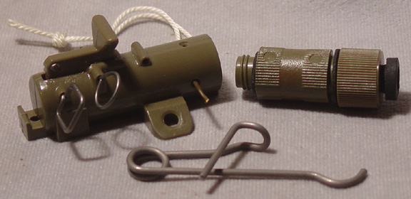
The firing device consists of three main parts, the head, body tube and
base coupler.
The head is made to fit inside the main body.
It consists of the body, release pin, loading spring and safety
pin. The body fits into the
main body tube and is crimped in so it cannot be removed.
The release pin fits through the bottom up through the top of the
body. The loading spring
fits over the release pin and is retained by a washer fixed near the
bottom. Once the release pin
is pushed up, the safety pin fits through holes in the body and pin to
hold it in place. A split
ring is attached to the end of the release pin to allow a wire to be
attached.
The body tube is threaded internally at the bottom and is cast with the
constricting well as an integral part.
It contains the firing pin and firing pin spring.
The firing pin is a single piece turned down to form a striker
head and shaft with a ridge on the top end.
The top end is split to accept the release pin.
The striker and spring are pushed up with the split end passing
up through the constricting well to engage the release pin.
The release pin pushes the striker end apart so that it cannot
pass through the constricting well.
The main body tube is cast with a lug on the side.
The lug has a hole through it to attach a short piece of cord to
act as an anchor. The cord
is used to anchor the device in place.
The base coupler contains the primer and screws into the bottom of the
body tube.
When the device is set, a pull of 3-5 pounds on the wire will pull the
release pin up against the pressure of the loading spring.
As the pin is pulled up it pulls out of the split end of the
striker. When the release
pin pulls out of the striker the end is free to close and under pressure
of the striker spring is forced down out of the constricting well and
down onto the primer in the base coupler.
The primer will fire into the detonator attached to it causing it
to fire.
The firing mechanism is painted olive drab.
The devices made in WWII are darker than those manufactured post
war and are not marked or are marked in yellow.
Post war devices have a lighter green wash and have markings in
yellow.
In February of 1943 Mr. Roysdon
of the Engineer Board asked the A. C. Gilbert Company to design a pull
firing device that would also fire on release of tension on the trip
wire. The company designed
the T3 Pull Release firing device, later standardized as the “Firing
Device, Pull/Release, M3”. The first order for 1000 devices was then
issued to the company on 3 August 1943.
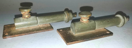
In February 1942 1st
Lt. W. L. Erhardt of the Engineer Board, Fort Belvoir, VA gave the task
of producing the pressure switch to the A. C. Gilbert Co.
The firing device was a copy of the British Pressure switch (No.
2 Pressure, Mk. I) with the exception of using an American style base
coupler. The British switch
had been introduced in 1941 and was well proven.
Several improvements were suggested by the company including
using a keyhole type trigger rather than the hardened shear pin.
This also had the effect of allowing the firing device to be
reused in training. The
company produced some 670,000 of this model.
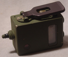
The device consists of a body,
pressure head, base plate, and base coupler.
The main portions are made of brass with the base plate made of
steel. The base plate is 1.5
inches wide and 2.5 inches long with two anchor holes in opposite
corners. The body is mounted
on the base plate by two flat head bolts through the bottom into the
wide end of the body. The
body is brass with a wider end that contains the firing mechanism and a
thinner barrel portion that contains the striker and spring and is
threaded to accept the base coupler.
A smaller diameter hole is blind drilled into the head to accept
the striker shaft. A larger
hole is drilled through the top of head to accept the pressure head.
The pressure head is made of brass and has the bottom thinned
down to a trigger pin with a keyhole in it.
When assembled, the striker and
spring are placed into the body barrel, the pressure head and spring are
placed into the hole in the head and pressed down so the large portion
of the keyhole lines up with the small hole in the head.
The striker is forced against the pressure of the spring into the
small hole and through the hole in the pressure head.
When pressure is released on the head, the spring forces the head
up engaging the small end of the keyhole with the groove in the striker
preventing the striker from moving.
A safety clip is engaged between the head of the pressure head
(over the spring) and the body preventing the head from moving down.
When laid and the safety clip is
removed, a pressure of 20 pounds or more will cause the pressure head to
move down bringing the large end of the keyhole in line with the striker
shaft disengaging it from the striker groove.
This allows the striker spring to reassert itself and push the
striker forward until it strikes the percussion cap in the base coupler.
The cap fires and initiates the detonator attached to the base
coupler and in turn the main charge.
The A. C. Gilbert Co. in
collaboration with the Engineer Board, redesigned the firing device in
August 1942 so that it could be made from die cast zinc alloy.
This change simplified production, saved critical brass, include
a positive safety and reduced the weight of the device.
It was adopted in mid-1943 to replace the old style.
The first contract for this version was for 685,000 firing
devices.
The device consists of a body,
pressure head and base coupler.
The body is die cast zinc alloy made in a single piece.
It has a basically tubular body with a flattened base for about
half the length. Protruding
out from the base are three lugs that are used to fasten the device in
place. A hole in the top of
the body fits the pressure head.
The striker which has a firing pin head at one end and a groove
in the shaft at the other fits with the striker spring inside the body.
The pressure head has a flat top with a shaft on the bottom.
There is a keyhole in the lower portion of the shaft.
The base coupler is the standard M1 base coupler.
When assembled, the striker and
spring are put into the body and forced into the body so that the shaft
of the striker fits into a small hole in the back that connects with the
hole in the top of the body.
The pressure head with spring are pushed down so the shaft of the
striker fits through the large upper hole in the keyhole.
Once the shaft of the striker is pushed through the pressure head
is released so that the small portion of the keyhole engages in the
groove in the striker shaft.
This holds the striker back in the cocked position.
A safety clip fits over the spring on the pressure head
preventing its downward movement.
A positive safety pin is fitted through holes in the side of the
body in front of the striker.
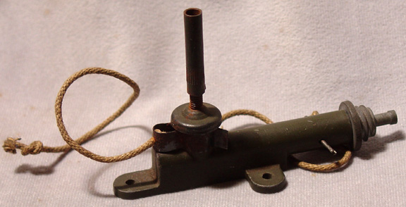
The device is supplied with an
extension rod. The rod
consists of a length of threaded rod mounted on a cup and an internally
threaded tube. The cup press
fits onto the pressure head.
The extension provides between 1.25 and 2.25 inches of extension.
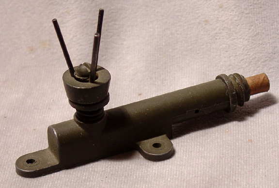
In 1943 The A. C. Gilbert Co.
modified the M1 pressure Firing Device to add a three pronged adapter to
the pressure head. The three
pronged head was copied from a German mine igniter and allowed better
camouflage for the device.
The modifications were minor and were done quickly.
The device consists of a body, pressure
head and base coupler. The
body is die cast zinc alloy made in a single piece.
It has a basically tubular body with a flattened base for about
half the length. Protruding
out from the base are three tabs that are used to fasten the device in
place. A hole in the top of
the body fits the pressure head.
The striker which has a firing pin head at one end and a groove
in the shaft at the other fits with the striker spring inside the body.
The pressure head has a flat top with a shaft on the bottom and a
threaded hole in the top.
There is a keyhole in the lower portion of the shaft.
The base coupler is the standard M1 base coupler.
When assembled, the striker and
spring are put into the body and forced into the body so that the shaft
of the striker fits into a small hole in the back that connects with the
hole in the top of the body.
The pressure head with spring are pushed down so the shaft of the
striker fits through the large upper hole in the keyhole.
Once the shaft of the striker is pushed through the pressure head
is released so that the small portion of the keyhole engages in the
groove in the striker shaft.
This holds the striker back in the cocked position.
A safety clip fits over the spring on the pressure head
preventing its downward movement.
A positive safety pin is fitted through holes in the side of the
body in front of the striker.
The device is supplied with an
extension rod and three pronged adapter.
The rod consists of a length of threaded rod and an internally
threaded tube. The three
pronged adapter has a base with three wire prongs attached by a bolt to
the top. The adapter can be
screwed directly onto the pressure head or can be attached to the
extension rod which is then screwed onto the pressure head.
When laid and the safety pin and
clip are removed, a pressure of 20 pounds or more will cause the
pressure head to move down bringing the large end of the keyhole in line
with the striker shaft disengaging it from the striker groove.
This allows the striker spring to reassert itself and push the
striker forward until it strikes the percussion cap in the base coupler.
The cap fires and initiates the detonator attached to the base
coupler and in turn the main charge.
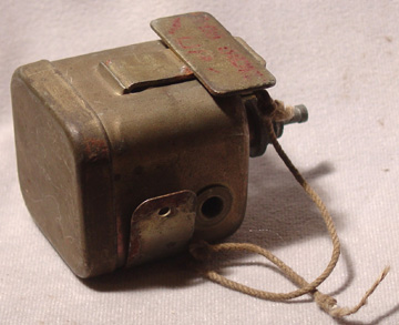
This firing device was
introduced during WWII. It
is strictly an American design not taken or designed from any devices in
service with anyone else. At
first glance, it seems an overly large but it is designed that way to be
the same size as the standard US Army ½ and 1 pound demolition blocks.
One of the manufacturers of this device was the Geometric
Stamping Co. of Euclid Ohio.
The body of the device is a stamped
sheet metal box with rounded edges.
One end is open, the other closed with a stem spot welded on to
hold the base coupler. The
other end is closed by a removable stamped sheet metal cap.
The firing pin is inserted in a small hole in the centre of the
stem and held on by a press fit washer.
The firing hammer mechanism is riveted inside just above the
stem. On the outside of the
device, held on by the same rivets as the firing mechanism, is a bracket
for the safety pin and release plate.
The release plate is formed of sheet metal with a tail, plate and
a portion formed on the bottom to fit into the bracket.
There are two holes punched in either side of the device opposite
each other. There are small
tubes inserted in the holes that leave a space between them.
These holes are used for a positive safety in that a nail or rod
inserted through the holes will block the travel of the firing hammer
before it can strike the firing pin.
There are mounting brackets spot
welded onto the bottom of the body.
The earlier (WWII) firing devices have a mounting bracket ¾ inch
wide at 90 degrees from the stem with a single hole on either end.
These are bent up around the device until required.
A later version has the mounting bracket turned 90 degrees and is
angled in appearance. At the
back end (over the end cap) is a single hole, at the other end, which is
bent up around the stem there are two holes.
Other than the mounting brackets, the devices are identical.
In June of 1943, Captain Terbert of the Engineer Board gave the A. C. Gilbert Co. a model of a release device and asked them to incorporate some changes to the model and make samples. Once the samples were produced and approved a number were made for training. During training it was found that further changes and improvements were required. Several revised models were produced until one finally satisfied all the requirements of the Engineer Board. The final model was standardized as the “Firing Device, Release, M5”
A minimum weight of 5 lbs is
required to hold the release plate down when laid.
When the weight is removed the striker spring reasserts itself
and causes the striker to rotate.
The rotating striker pushes up on the release plate until it is
pushed out of the way and the striker is free to completely rotate and
hit the percussion cap in the base coupler.
The percussion cap will cause the detonator attached to the base
coupler to fire.
In September 1942 Major Erhardt
and Mr. J.P. Roysdon of the Engineer board presented the A.C. Gilbert
Co. with the project of developing a friction igniter, similar to a
German device. The device
was to be made of plastic and had to be small, waterproof, and as
non-metallic as possible.
The company produced many lots with slight revisions before it finally
met all the requirements.
This was the “Pull Type Firing Device, T2” which was later standardized
as the “Firing Device, Pull, Friction, M2”.
The construction of this device almost eliminated the use of
critical war materials.
While the device was developed and test lots made by A.C. Gilbert Co.
final production was passed to another company.
During development of the T2,
there were two other models produced, the T2A and T2B.
These differed slightly from the T2 and test lots of 500 each
were produced in 1944.
Unfortunately no other information is available.
The entire device is constructed
of black bakelite and a small amount of steel.
The body is cylindrical and has a non-removable base coupler on
the bottom. The body
contains a pellet of friction compound in the top of the base coupler.
A steel wire coated with red phosphorous fits through the top of
the body, through the pellet and into the stem of the base coupler.
A safety pin fits through the side of the body and through a
twisted portion of the wire.
A coil spring is attached to the looped end of the wire.
The base coupler has a celluloid cup filled with desiccant
protecting it.
For use a detonator is crimped onto the
base coupler. A slack trip
wire is attached to the spring.
When a load of 3-9 pounds is applied to the trip wire, it will
stretch the spring then snap the friction wire out of the device.
That causes the red phosphorous on the wire to pull through the
friction compound causing a flame to flash through the base coupler and
ignite the detonator. The
device is not totally waterproof and should if possible be used where it
is protected from moisture.
There is apparently a zinc alloy
bodied version. Little is
known about this version other than it operates in exactly the same
manner. Possibly this is a
T2A or T2B.
Development of this igniter started as a British requirement for a
method to initiate several Limpet mines at the same time without the
need to connect them with primacord.
The SOE (Special Operations Executive) requested help from the
OSS (Office of Strategic Services) in the development of a sympathetic
fuze. After the OSS
initiated the development, the Army and Navy found they also had use for
such a device. After much
research and development, the resulting device became the “M1 Concussion
Firing Device”. It is a
mechanical device actuated by the concussion of a nearby explosion.
In use, a single explosion will cause any charges equipped with
the firing device within range of the initial explosion and others
within range of the other devices to fire.
These were introduced for use
where a short delay was desirable.
They could be used in assault demolitions or rigged with a trip
wire. They are waterproof
and could be used underwater.
No information has been found to differentiate between the M1 or
M1A1.
This is a US Navy device
modified from the earlier Mk. 1 Mod 0 device.
Depending on how it is set it can operate as a pressure, pull or
release device.
In 1943 the OSS arranged for the
production of AC delays in the US as the British were having problems
producing enough. The
American version is an exact copy with minor cosmetic differences.
The AC delay was used throughout the remainder of WWII and was
later adopted and produced by the CIA.
It was also used by the Army and Navy.
The AC delay saw considerable use in Viet Nam.
They are comprised of a round
brass body made with a two stepped threaded end, the smaller set of
threads for the burster and the larger set to screw into the limpet or
charge container. It could
also be fitted with a fuse cap instead of the burster.
The opposite end is threaded to fit an end cap that is drilled
and threaded to accept a thumb screw. The
most obvious difference between the British and American production is
the thumb screw. The grip on
the British version is rectangular, the American is oval.
A safety pin with cord attached
fits through the end cap and thumb screw preventing it from being
screwed in. Contained within
the body is a spring loaded striker that is held in the loaded position
by a celluloid disc attached to a tapered tail on the striker.
Lint is packed in a brass sleeve screwed into the body just above
the striker holding the striker and disc in place.
American celluloid is different than British celluloid and did
not work properly. Until a
suitable substitute was found the OSS obtained British celluloid which
was used until the end of WWII.
By then a suitable substitute had been found and was used for
post war production. All
threaded joints are fitted with rubber washers to waterproof the device
to a depth of 70 feet.
The CIA continued with production of
the AC Delay post WWII. The
CIA produced a Mk. II version in the 1950’s and a Mk. III version in the
1960’s. Exactly what the
differences between the three versions are is unknown at this time.
The CIA also introduced an incendiary
head to replace the burster.
The incendiary head would ignite immediately upon being struck by the
striker and would burn very brightly with an intense heat for 4 to 6
minutes diminishing after that to being completely expended in 10
minutes.
The M142 was introduced into
American service in about 1972.
The device is issued in a round
plastic case containing everything required to set the device in any
mode. Contained within the
case is the device, roll of steel trip wire containing 15 metres of
wire, a strip of tape containing screws and nails, a tension release
attachment, base coupler and an instruction sheet.
The coupling base is also issued separately.
Early issues of the device were packed in round tin boxes.
The device is made of olive
green plastic, as are the base couplers.
The base couplers have a yellow or brown band around the centre.
The M147 is not used in general demolitions.
It was primarily designed to provide Special Forces with a device
that could accurately initiate a timed demolition.
It is very reliable, not effected by temperature to any great
degree, has accurate timing and can be used underwater.
It is also hardened against outside sources of electro-magnetic
interference to prevent premature firing from those sources. The device
covers all time ranges from 5 minutes to 30 days.
- lifting the arming tab 180 degrees from the body.
The “S” on the rotor should be beside the indicator mark.
-Rotate the rotor 90 degrees until the “T” is
beside the indictor mark.
This activates the battery.
The LCD display should read all 8’s, diamond symbols and underscores.
-The time is set by pushing the left button once so
the display goes blank, press it once more and the display will read all
zeros with a 5 on the right.
An underscore(cursor) will be under the left hand zero.
Each time the left button is pushed the cursor moves one position
to the right. There are
three sets of two digits representing days/hours/minutes reading from
the left. To set the time
position the cursor under the digit desired and hold the left button
down, press the right button to change the digit.
Each press on the right button moves an increment of one.
Release and press the left button to move to the next digit.
Continue until the desired time is set.
-Take the arming tab in one hand and with the other
press down the locking button, rotate the rotor until the “A” is aligned
with the indicator mark.
Check the display to ensure the minutes and seconds of the 5-minute
arming delay is showing.
-Turn the
rotor back to the “T” position, the arming delay will stop and the
display should now show the delay time.
-Install the M7 detonator using the coupling nut.
-Arm the device by turning the rotor to the “A”
position. This starts the
5-minute delay again and the display should show the countdown of the
delay.
-Lower the arming tab and connect the device to the
charge.
Once
the 5-minute delay has elapsed the display will show a pair of flashing
diamonds. The internal
piston actuator functions removing the safety interrupter and putting
the primer in direct line with the detonator.
The safe/arming indicator changes from a green “S” to a red “A”.
The device is armed and functioning.
Once functioned this device cannot be stopped or reset.
When the delay time expires the M147 applies power to the primer
that then fires the detonator and explosive charge.